
The Gent


The Gent
This project is now available by Whadda! Click here to go there.
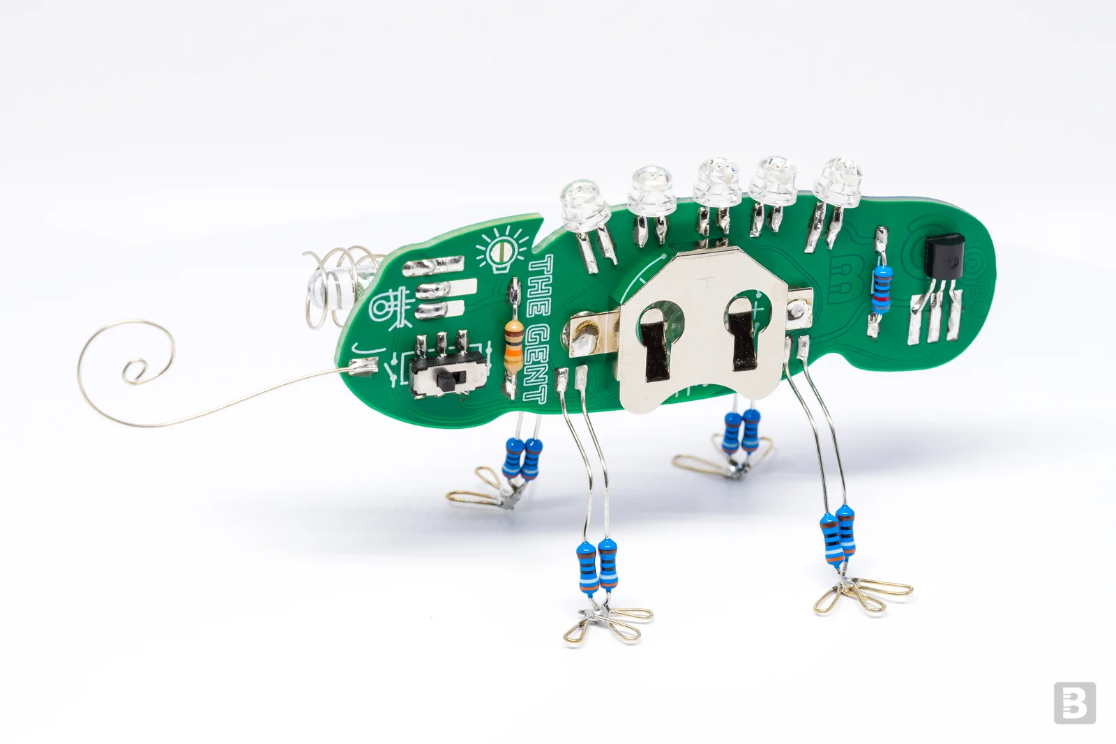
A playful electronics chameleon that lights up in the dark
We've collaborated with Eurocircuits to manufacture this unique two-tone circuit board that transitions from blue to green. When The Gent's 'eye' (a phototransistor) is pointed towards a light the five LEDs are off. As soon as light is blocked from The Gent's view it gracefully shows its colours.
(Note: The Gent isn't perfect :-/ See 'Rework/problems' section below.)
The Gent was project #10 of the Boldport Club.

What’s included
1x DPDT slide switch, C&K JS202011SCQN
1x 5mm phototransistor, Kingbright PT333-3C
3x Green 5mm LED, Kingbright L-9294CGCK
2x Orange 5mm LED, Kingbright L-9294SECK
1x CR2032 battery clip, Multicomp BC-2001
1x N-channel MOSFET, Fairchild 2N7000
8x 390Ω through-hole resistor, Multicomp MCF 0.25W 390R
1x 820Ω through-hole resistor, Multicomp MF25 820R
1x 10KΩ through-hole resistor, Multicomp MF25 10K
1x Lovely two-colour PCB
The circuit
A phototransistor acts as a light detector; conducting when it 'sees' light. When there is light pointing at the phototransistor, the MOSFET is off, which means that the LEDs are also off. When there's darkness, the MOSFET's gate is pulled 'high' and turned on causing the five LEDs to turn on as well.
Infographic | PDF
Assembly
Assembly of the kit is relatively straightforward using the assembly guide. Below are a few things to note.
The kit includes five LEDs; three green and two orange. without being powered they look the same. Try to figure out the colour of the LED before soldering it, but make sure not to burn them with excessive current. If you have one, our LIGEMDIO project is perfect for this :)
The 'legs' are a part of the circuit. Don't let the leads between the board and the resistors' bodies touch.
There is a small amount of current flowing through the circuit even when the LEDs are off (about 300µA). We recommend that you switch off the circuit when it is not in use to avoid battery waste.
Solder the battery holder last, as this makes soldering the other components easier. Also make sure that the battery holder's metal body doesn't touch any of the circuit contacts or components.
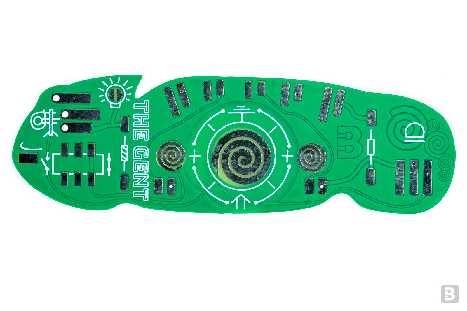
The bits pointed by the arrows were meant to be covered. The battery holder may short the battery to the power plane, which will cause the switch to not function and the board to be always 'on'.
Rework/problems
The bits pointed by the arrows were meant to be covered. The battery holder may short the battery to the power plane, which will cause the switch to not function and the board to be always 'on'.
Unfortunately, despite best efforts sometimes a circuit board doesn't come out perfect. Our The Gent has a fault: the battery holder's positive terminals may be shorted to the power plane through exposed copper around the two swirly side contacts of the holder.
These are the bits that need not be shorted to the battery holder positive terminals.
These are the bits that need not be shorted to the battery holder positive terminals.
A good solution is to use a bit of Kapton tape to cover the exposed bits that are meant to be covered by soldermask and then solder the battery holder as normal. Perhaps more immediately practical is to cut the battery holder using strong wire cutters so that its positive terminals avoid the problematic areas and then carefully apply solder. One can also try to carefully cut out the unwanted exposed bits so that they are no longer connected to the power plane. Finally, one could simply eject the battery when the board is not in use.
Another issue
There is solder-blob-jumper that can be shorted temporarily in order to light up the LEDs for testing. This isn’t a very good circuit as it could cause excessive current draw when the the phototransistor is facing a bright light. So please just don’t use this optional “feature”.
Further information
Community contributions for this project
Open source circuit board design files
