
Pease


Pease
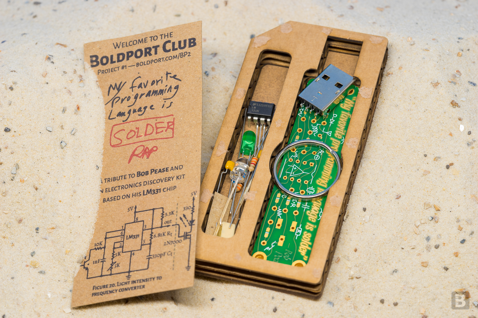
A tribute to legendary engineer Bob Pease
Bob Pease was an analogue design expert and technical writer of legendary status. He had the unique ability to communicate very technical topics in a relatable style, character, and authority, and thus becoming an educator to generations of engineers. One of Pease's most memorable sayings was 'My favorite programming language is... solder', which captures so much of our love for electronics and creating things with our minds and hands.
An introduction to this board is here.
Pease was project #1 of the Boldport Club.

What’s included
5KΩ potentiometer, Bourns, 3361P-1-502GLF
USB type A connector, Multicomp , MC32603
LM331, TI, LM331N/NOPB
nMOS FET, Fairchild, 2N7000
Green LED, Kingbright, L-1503GD
Phototransistor, Vishay, BPW96C
4.99KΩ, 3.3KΩ, 330Ω, 10KΩ, 6.81KΩ resistors
330pF, 1nF capacitors
2 PCBs
Assembly
One should start by looking through the datasheet of Pease's 'voltage-to-frequency converter', the LM331, which is the heart of the circuit. Specifically, look at Figure 20 (this circuit is depicted on the cover of the kit, with the addition of a FET, resistor and LED). The complete circuit is also shown on the back-side of the board; keep referring to these diagrams as you solder.
If you'd like to challenge yourself, stop here and figure things out. Otherwise, continue reading...
Make sure to solder the components on the right side of the board! (Top side, the one with Bob's quote.)
You may know that the value of a resistor can be read by the colour bands on it. Wikipedia has a good article explaining how to read these values. Match those to the positions on the circuit board. (One value is not exactly the value specified on the board; can you guess why?)
Capacitors also have numbers on them that indicate their value. Here's an explanation on how to make sense of these numbers. So, for example, one of the capacitors says '10 2' , so that's 1000 pF, or 1 nF.
The phototransistor — the one with the clear dome — is an interesting component. Transistors typically have a 'gate' or a 'base' that acts like a light switch. With a phototransistor, the presence or absence of light acts as the switch, and that's why it has only two terminals (pins) instead of the normal three. Just make sure to connect the 'emitter' (long leg) to ground (triangle symbol).
The n-channel field-effect transistor (FET) needs to be soldered onto the board carefully. Look at the drawings on datasheet and the markings on the board to make sure you get it right.
The potentiometer can be soldered as a surface mount component, or as a through-hole component if you bend the pins. It doesn't make any difference functionally; use it to practice your SMD soldering!
Power can be supplied to the board either through the USB connector or the large holes on the other side, as the markings show (5V or ground). Never connect power to both at the same time. Soldering the USB connector is optional, so don't if you feel that you won't like or use it. If you do, make sure to solder the USB connector the right way, on the top side of the board.
Finally, the green LED has a long and a short leg ('anode' and 'cathode', respectively). The long leg should be placed right after the 330Ω resistor and the short leg towards the drain (marked 'D') of the FET.
Now that you're done, experiment. Connect an oscilloscope and see what happens when you turn the potentiometer. What happens when you change the values of components according to the operating explanation in Section 9 of the LM331 datasheet. Can you, for example, determine which component values and conditions will have the LED be half-second on and half-second off?
Additional information
Community contributions for this project
Open source circuit board design files
