
Edge detect ad nauseam
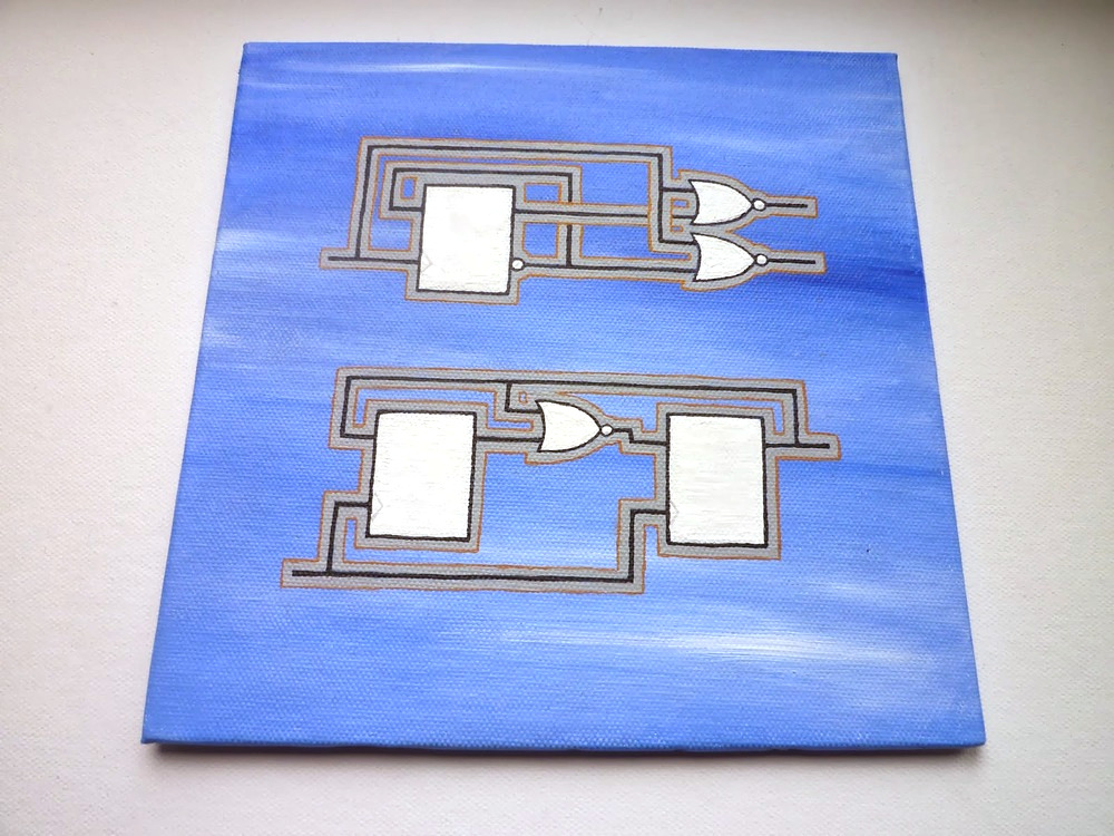
Some logic circuits from the Second Edition I painted on canvas. More here.
Yesterday I've received the third edition of The Art of Electronics by Horowitz and Hill -- or 'the bible' for short. I've been drooling over it for hours; as an engineer it's the closest feeling to your favourite band releasing a new album. H&H are the engineering world's rock stars going on a triumphant world tour.
Going through the book I came across one of my favourite tiny logic circuits, the 'edge detect' (or 'single-pulse generator'), where a pulse the length of a single clock period is generated from an asynchronous, other clock domain, or possible 'noisy', source into a synchronous circuit. For FPGA design, I often use a similar circuit to debounce external inputs or for modules that expect a single pulse input signal -- reset, START, etc. -- and I'm uncertain that they will be. Below is H&H's version in Figure 10.75 (which immediately "offended" my FPGA-centric view... more on that later ;):

Page 739 of The Art of Electronics Third Edition
I'm certain that H&H had good reason to draw the circuit like they did, but I prefer to do away with the double inversion on the feedback.
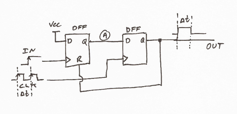
We have two edge-triggered flip-flops, the second clocked by the synchronous clock and the other by the input signal (!) The output controls the reset input of the first flip-flop.
H&H challenge the reader to create a timing diagram
Note that even though it's not specified, the reset must be asynchronous, otherwise the circuit won't work. We could end it here, but I'm pretty sure that H&H were trying to tease out more insight from the reader.
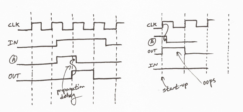
Consider what happens at power-up when the state of the flip-flops are unknown (remember those pesky red 'unknown state' during behavioural simulation?) H&H say that this circuit is glitch-free. It is. But, we could get an unwanted pulse if the first flip-flop starts out in a high state and the second in low state (see right side of diagram above). This may or may not affect the functionality of your circuit; that depends on what it's 'driving'. This could keep you debugging your apparently random-failing circuit for days in the lab. What other potential issues did I miss?
Now, why was I "offended"? As an experienced FPGA designer, seeing a non-clock signal going to a clock input feels like a punch to the stomach (as it should!). It's a major no-no unless you really know what you're doing. This is because clocking resources are 'special' and are carefully crafted to deliver synchronous clock-edges to the entire 'clock tree' at the same time. They're not meant to be used for 'ordinary' signals -- 'local routing' exist for those -- even though it's possible to arm-twist the tools to do it. Implementing H&H's circuit as-is would generate a warning, or physical-synthesis would deal with it by 'understanding' what you 'mean' and re-jig the circuit to do the right thing, or re-route the input as a clock signal wasting a valuable resource. These outcomes are bad, bad, bad since the designer seems to get away with it and think that this practice is 'ok'. Besides, different tools would interpret the 'meaning' differently so you would be really pushing your luck with non-portable code, even between versions of the same tool. The tools should, ideally, produce an error and halt unless the designer presents a notarised note from a Registered Guru, such as Dave Vandenbout.
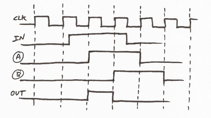
Here's the circuit I've been using for forever
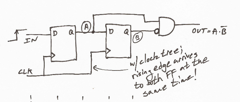
Luckily, most FPGAs have a deterministic start-up state ('low' unless otherwise explicitly specified) so the unwanted start-up pulse won't happen. The asynchronous input signal still needs to be longer than the clock period to guarantee that it'd get caught (H&H's circuit has the advantage of not suffering from this problem). Here's the timing diagram
and one possible Verilog implementation
// edge detect module
module edge_detect(
  input  CLK,
  input  RST,
  input  IN,
  output OUT
);

  reg a, b;

  // the edge detect signal is (b AND (NOT a))
  assign OUT = a & !b;

  always @(posedge CLK) begin
    // It's always good to have a reset condition, otherwise
    // the state of the register will show up as undertemined
    // in simulation ('x')
    if (RST == 1'b1) begin
       a <= 0;
       b <= 0;
     end
     else begin
       a <= IN;
       b <= a;
     end
  end

endmodule
Please add your thoughts in the comments!
UPDATE 2015-04-08: Thanks to 'Lampshader' over on Reddit for pointing out that I was originally wrong in saying that H&H's circuit would miss a shorter-than-a-clock-period pulse on the input.